There are many ways to update an embedded system in the field. Images can fly through the air one a time, travel by sneaker or hitch a ride on other passing data. OK, maybe that’s a stretch, but there are certainly a plethora of ways to get those sweet update bytes into a target system. How are those bytes assembled, and what are the tools that do the assembly? This is the problem I needed to solve.
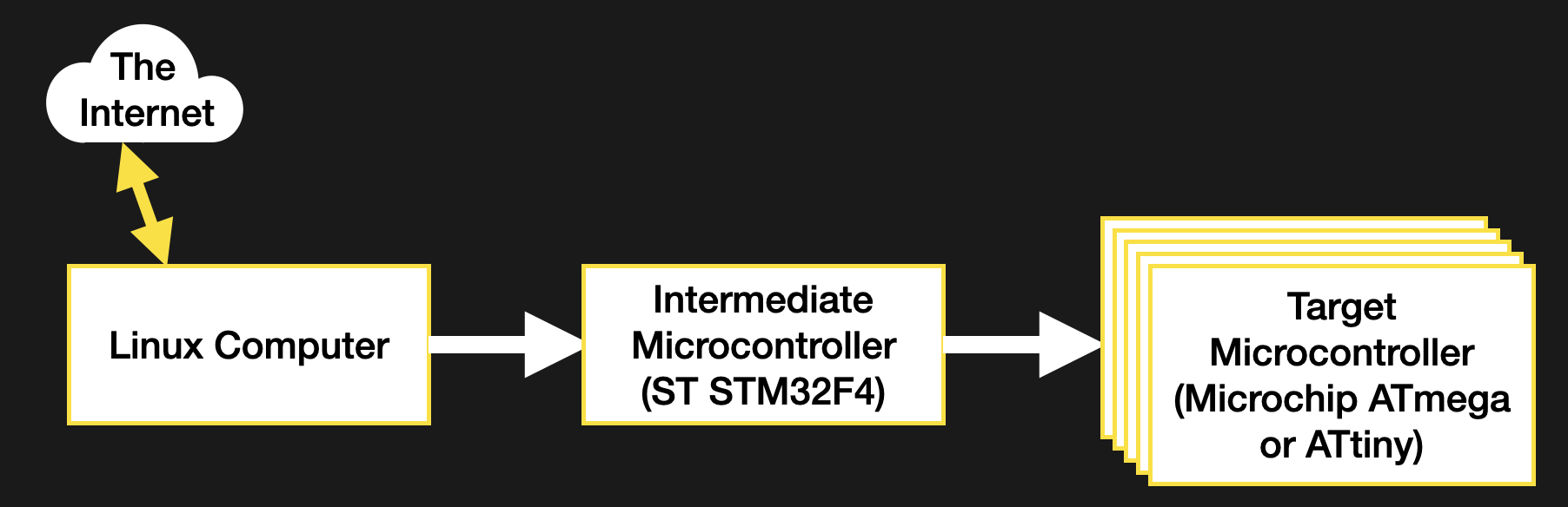
Recall, my system wasn’t a particularly novel one (see the block diagram below). Just a few computers asking each other for an update over some serial busses. I had chosen to bundle the payload firmware images into the binary for the intermediate microcontroller which was to carry out the update process. The additional constraint was that the blending of the three firmware images (one carrier and two payload) needed to happen long after compile time, on a different system with a separate toolchain. There were ultimately two options that fit the bill.
There’s more than one way to use the linker to stick binaries together — that’s its job after all. A typical compilation toolchain uses ld to string object files together, but there are other linker-adjacent tools which come in handy for playing havoc with the right kind of binary file. This method for bundling firmware images together will focus on a new tool in the GCC, objcopy.
To abuse the metaphor, objcopy is a bit of a utility knife for object file manipulation. The breadth of it’s functionally is wide but the specific thing we need here is the --update-section parameter, which allows us to replace a named section in an object file with another object file. So how do we get that section? That’s where a configuration file called a “linker script” comes in.
A detailed discussion of the usage of the linker script is out of scope here but for now let’s summarize it as, well, a script for the linker! A complete executable is composed of many different sections, and the linker script is what describes where they should go and how to refer to them. For instance, in a microcontroller the text section where the code-to-be-executed is stored is often placed in flash at an address where the micro will begin execution. The linker script is what describes the region where that data should go, and that it should be located in flash. We can use the same mechanism to inject a firmware payload into our image.
My first step was to describe two new sections, one for each new firmware image. The following segment shows the data section for the intermediate microcontroller, and the two payload sections I added below it.
/* Initialized data sections into "RAM" Ram type memory */
.data : { . = ALIGN(4); _sdata = .; /* create a global symbol at data start */ *(.data) /* .data sections */ *(.data*) /* .data* sections */ . = ALIGN(4); _edata = .; /* define a global symbol at data end */ } >RAM AT> FLASH
/* Below this point are the sections I added */
.payload1 :
{ . = ALIGN(4); BYTE(0x0); payload1End = .;
} >FLASH .payload2 :
{ . = ALIGN(4); BYTE(0x0); payload2End = .;
} >FLASH
This is a little cryptic, but it should be clear that payload1 and payload2 are both specially delineated sections which are to be placed in flash. With these defined, the linker will take care of ensuring the symbols are defined, the sections are large enough, and that they won’t overlap anything else. They will float along relative to their neighbors in the same order, keeping these two sections at the end of flash and the *end symbols at the end of their respective sections.
To access these sections at runtime we can refer to the named symbols payload1/payload1End and payload2/payload2End as extern symbols in our C source, but they’re also visible in the compiled binary. For this we need to use the Executable Linked File (ELF) that the linker produces as its final output. In my case this was the default output and was converted from an ELF to a binary to flash to the microcontroller. Depending on your platform this may or may not be the case.
The ELF file contains everything needed to run your program, including all the metadata and symbols the linker has at link time, whereas the binary may have these stripped out. If they are present than tools like objcopy can refer to them. At this point injecting the firmware is just a single well-formed command away. Convert the bin payload in question into an object file then use objcopy to inject it into the final binary like so
borgel$ objcopy --update-section .payload1=payload1.bin combined-firmware.elf
objcopy uses the same tricks as the linker to make everything fit and moves our symbols around as needed to mark the sections in question. Now the running firmware can get the size by subtracting the address of the start and end symbols, and refer to the payload memory as starting at the start address. Easy!
So why wasn’t this my final method for injecting payload firmwares? It requires a copy of objcopy that knows how to handle ELFs of the target architecture. In my use case I didn’t have such a toolchain available in the right place to make use of it, so I moved onto the next method.
If nothing more clever works, a binary is just a file to be edited. It’s not particularly elegant, but modifying the binary directly is nothing if not universally applicable, so long as you know the details of the file going under the knife.
Let’s start with attaching multiple binary files together. This turns out to be extremely straightforward; just concatenate them! The command looks like
borgel$ cat payload1.bin payload2.bin >> combined-firmware.bin
It’s that easy! I needed to get the combined file into the intermediate microcontroller, which turned out to be similarly straightforward. The microcontroller’s flashing tool will happily write the combined firmware to the device, placing the payload files in the right address. But how does the running firmware know where to look to extract the payloads? And how does it know know how large they are? For that we need to turn back to our friend the linker.
Keep in mind the files we have to work with are the final binary images without any of the embedded metadata in the previous method. And even if they were, this process needed to work without the processor-specific toolchain on hand. So what to do? When editing the ELF, we used the linker script to describe a new section in flash. We can use the same trick here to create a special “end of firmware” section and symbol. As long as the linker script orients it as the last element of the image to be written to flash, it will be guaranteed to float along and always stay at the end as the rest of the firmware grows and shrinks during development.
Now that we have an end of firmware flag we the puzzle can be solved. For simplicity, in this section I chose to place 8 magic bytes (as two uint32_t‘s) describing the size of the images to follow. In the future, if I need more flexibility I could place a file with a JSON object, some serialized msgpack, or anything else there instead. The final image looks like
[main firmware][8 byte size file][payload 1][payload 2]
But what happens if there is no payload appended? The intermediate microcontroller needs a way to tell if there is anything out there in the wilds of flash to search for. Erased flash might work (it should always read as 0xFF), but if the flashed image shrinks and I was unluckily on an erase boundary there might be valid-looking garbage data there instead of a fresh field of 0xFFs. To avoid this I turned to the linker once again.
The linker script allows for the definition of hardcoded bytes or byte patterns to fill a region. So I added two 4 byte check values in a region after the end of firmware flag. At runtime the firmware loads the payload firmware sizes from the end of firmware offset and compares them to the check values. If they match, it assumes no payload is present. The section defined in the linker script looks like this
.endmatter :
{ . = ALIGN(4); endmatterStart = .; LONG(0xDEADC0DE); /* Payload 1 size */ LONG(0xDEADBEEF); /* Payload 2 size */
} >FLASH
When the firmware is being bundled together, I truncate the main firmware file and remove the final 8 bytes to remove this section. Then I create a file containing the two payload sizes and concatenate it on. The linker guarantees that the last 8 bytes are always the check values (which can be confirmed with a hexdump). At this point the command looks like
borgel$ truncate -s -8 combined-firmware.bin
borgel$ cat size.bin payload1.bin payload2.bin >> combined-firmware.bin
The last piece of the puzzle is building that 8 byte size file. I wanted to embed the size as raw byte values (not ASCII) to force them into a constant size. For this we must reach all the way back to the beginning of this journey to again find xxd. Previously I used xxd to convert from a binary file to hex (in the form of C source), but the tool works in reverse as well, converting from a hex file to a binary. It’s not too picky, so all we need to give it is the starting address of the “hex file” to convert, then the series of bytes it should consume to produce the binary output file. All together that looks like
borgel$ printf '0: %08x %08x' `stat -c %s payload1.bin` \ `stat -c %s payload2.bin` | xxd -r -p - >lenfile.bin
and gives a file with exactly the contents we expect:
borgel$ stat -c %s payload1.bin
922
borgel$ stat -c %s payload2.bin
176
borgel$ hexdump lenfile.bin
0000000 00 00 03 9a 00 00 00 b0
0000008
That does it! Almost anticlimactically, final sequence of commands turns out to be just three shell commands
borgel$ truncate -s -8 combined-firmware.bin
borgel$ printf '0: %08x %08x' `stat -c %s payload1.bin` \ `stat -c %s payload2.bin` | xxd -r -p - >lenfile.bin
cat size.bin payload1.bin payload2.bin >> combined-firmware.bin
There we go! Two more methods for editing binary files. Between these and the first two options described, most use cases should be covered. Most of these techniques should serve well for any assets which need to combined; think adding sound effects or images to a system without external storage to hold them.
Hopefully you now feel empowered to slice and dice your way to binary payload victory, no matter the geometry in question.
Credit to this excellent article “Embedding binary data in executables” by [Christian Stigen Larsen] in 2016 for the kernels of some of these ideas. If you’re interested in another one or two choices it provides an excellent summary of some other options.
Recent Comments